
Page 4 - HIOKI 2017 Field Measuring Instruments
P. 4
4 About the Catalog
About the catalog l This catalog provides an overview of carefully 1 About the marks
selected product specifications with a focus
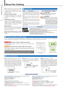
on field measuring instruments. For more CE marked ISO 14001/ ISO 9001 certified
information, please see individual product catalogs
or HIOKI’s website. The CE mark certifies that a product complies with electrical ISO14001
safety standards established by European Community
l How to search for products directives (EC directives). These EC directives require HIOKI is certified under the international
This catalog is designed to make it easy to find conformance of a product to EN/IEC standards for electrical standard ISO 14001 for environmental
the product you’re looking for. Use the table safety. management systems.
of contents at the beginning (p.3) to search by •HIOKI's products bearing the CE Mark are designed to
category. confirm to the Low Voltage and EMC directives based on ISO9001
the EC directives.
l Dimensions and mass •The Low Voltage directive is applicable to products HIOKI's product design and development,
Exterior dimensions exclude protrusions, and operating from 50 to 1000V AC and 75 to 1500V DC, and manufacturing and sales and service operations,
are given in order of width(W), height(H), and require protection from electrical hazards such as electric including repair, inspection and calibration, with
depth(D), in mm units. Indicated weight represents shock. regards to our recording devices, component
an approximation of the mass of the main unit •The EMC directive requires suppression of emissions measuring instruments, signal generators, data
only, not including case, accessories, etc. of harmful electromagnetic radiation, and the ability to loggers, environmental measuring instruments, safety
withstand exposure to external electromagnetic radiation measuring instruments, clamp sensors, power meters,
l Battery labeling without malfunction. field measuring instruments, as well as their integrated
Battery labeling complies with IEC international modules and options, are certified by the international
standards and includes R6P (AA), R03 (AAA), 6F22 standard ISO 9001 for quality management and quality
(9 V), LR6 (AA alkaline), LR03 (AAA alkaline), and assurance. (Remote measuring systems are excluded.)
CR2032 (button-cell lithium).
*For more information and to download the certificates, please go to www.hioki.com.
For more information about how to contact
HIOKI, please see the last page of this Trademarks
catalog.
*The Bluetooth®word mark and logos are registered trademarks owned by Bluetooth SIG, Inc. and any use of such marks
by HIOKI E.E. CORPORATION is under license.
*Android, Google Play and the Google Play logo are trademarks of Google Inc.
*iOS is a registered trademark of Cisco Technology, Inc. and/or its affiliates in the United States and certain other countries.
*iPhone, iPad, iPad mini, iPad Pro and iPod touch are trademarks of Apple Inc.
*Apple and the Apple logo are trademarks of Apple Inc. App Store is a service mark of Apple Inc.
*Microsoft, Windows, Windows Vista, and Excel are either registered trademarks or trademarks of Microsoft
Corporation in the United States and/or other countries.
*Other trademarks and trade names are those of their respective owners.
2 Rectification Methods: True RMS and Mean
There are two methods for converting current into RMS values: the true RMS method (true RMS value indication) and the mean method (mean rectification RMS value
indication). Although both methods yield the same value for undistorted sine waves, distortion of the waveform causes the values to diverge.
True RMS RMS value method (true RMS value indication) ■ Comparing distorted current True RMS clamp ammeter
values from an inverter, etc. Mean-type clamp ammeter
The waveform including harmonic components is calculated according to an RMS calculation
formula and displayed. Current waveform from an inverter
(primary side)
MEAN Mean method (mean rectification RMS value indication)
The input waveform is treated as an undistorted sine wave (single frequency only). The AC signal
mean is calculated, converted to an RMS value, and displayed. The measurement error increases
when the waveform is distorted.
*Widespread use of equipment such as inverter devices and switching power supplies has made it
more common for current waveforms being measured to be distorted. It is recommended to use a
measuring instrument that uses the true RMS method to ensure accurate measurement.
3 Accuracy and tolerances
l f.s. (maximum display, or length of scale, ... full-scale) l rdg. (displayed or indicated value, ... reading value) l dgt. (digital resolution, ... digit)
Signifies the maximum display (scale) value or the This signifies the value actually being measured, i.e., Signifies the smallest display unit on a digital measuring
length of the scale (in cases where the scale consists the value that is currently indicated or displayed by the instrument, i.e., the value displayed when the last digit
of unequal increments or where the maximum value measuring instrument. on the digital display is "1". Essentially, this indicates an
cannot be defined). In general, this is the range value error of 1 digit (based on decimal processing in analog-
(the value written on the range selector, or equivalent) Measuring 100 V to-digital conversion), but in actuality this is the digit
currently in use. However, be aware that in cases where using the 300 V error combined with the f.s. error converted to a fraction
the maximum display value is 2000V but the range range of a digit unit. The accuracy associated with a particular
value is only 600V, the maximum display value (scale measured value as shown in the product specifications is
value) is still used as the f.s. value. derived from these values.
300V range In the 300 V range,
the 0.1 V digit is
the smallest digit.
Example accuracy calculations
Example accuracy calculation 1 (when the accuracy notation combines rdg. and dgt.) Example accuracy calculation 2 (when the accuracy notation combines rdg. and f.s.)
Accuracy specification: ±1.0% rdg. ±3 dgt. Accuracy specification: ±0.2% rdg. ±0.1% f.s.
Measurement range: 300.0 V Measurement range: 300.00 V
Measured value: 100.0 V Measured value: 100.00 V
Since the value being measured is 100.0 V: Since the value being measured is 100.00 V:
(A) Reading error (±% rdg.): ±1.0% of 100.0 V = ±1.0 V (A) Reading error (±% rdg.): ±0.2% of 100.00 V = ±0.20 V
(B) Digit error (dgt.): Since the maximum resolution is 0.1 V, ±3 dgt. = ±0.3 V (B) Full-scale error (±% f.s.): ±0.1% of 300 V = ±0.30 V
(C) Total error (A+B): ±1.3 V (C) Total error (A+B): ±0.50 V
Based on the total error (C), the error boundary values for a measured value Based on the total error (C), the error boundary values for a
of 100.0 V would be 98.7 V to 101.3 V. measured value of 100.00 V would be 99.50 V and 100.50 V.